RTC Battery Information
The MityDSP-L138 family of modules have an on-board RTC that can be powered by a battery if designed into your carrier board.
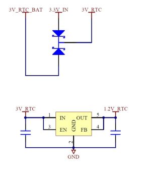
Note that the RTC battery input scheme was developed for use with a button cell battery and was not designed with super capacitor circuits in mind. As such if you do decide to utilize a super capacitor circuit note that the module will NOT re-charge the capacitors. Below is an image of the RTC battery input circuit on each module.

If battery backed RTC use is desired than the external battery should be hooked to Pin 35 of a module. It is also recommended that the voltage being supplied to the RTC voltage input pin be greater than 2.5V to guarantee operation.
If battery backed usage is not needed than Pin 35 of the module may be left floating and the RTC will function while power is applied to the module due to the Diode-Or circuit as shown above.
Current Draw
Typically when the module is powered off it will draw ~10uA to power the RTC.
Please reference our PCN 20120612000 for further details on RTC current draw.
Battery Life
If a battery such as the one used on the Industrial IO Board is used (BR-1225) a battery life of approximately 6 months is expected (in absence of module power). It is possible to select a larger battery for extended battery life. Please contact us for further details about recommended battery options.
RTC calibration
Like many Tuning-Fork Crystal based RTC devices the OMAP-L138 RTC will likely need to be calibrated to achieve near zero PPM time keeping. Please review TI's RTC Guide (http://d1.amobbs.com/bbs_upload782111/files_38/ourdev_628188IUHKKG.pdf) for specific details, a copy is attached. Please contact Critical Link if you require further information.
Go to top

