Hardware Differences from Beaglebone
The following items are differences between the MitySOM-335x Maker Transition Kit (MTK) and Beaglebone Black (BBB) design.
Electrical Differences
- Ethernet Phy
- MTK uses KSZ9031 instead of LAN8710A
- KSZ9031 used on the full-size MitySOM-335x Dev Kit.
- KSZ9031 connected to the RGMII1 interface (LAN8710A uses MII1 on the BBB).
- Ethernet reset tied to a dedicated GPIO instead of SYS_RESETn.
- Phy address of 010 is used instead of 000.
- i2c2
- The MitySOM-335x uses the i2c2 bus on-board the SOM, so the i2c2 pins on the expansion header were replaced with the i2c0 equivalents
- P9 Pin 19 on the BBB uses ball D17 while the MTK uses C16 (I2C0_SCL).
- P9 Pin 20 on the BBB uses ball D18 while the MTK uses C17 (I2C0_SDA).
- i2c1
- i2C1 is used on the SOM, but the pins are available on the edge
- If you have a cape that is currently using i2c1, you will need to connect to balls H17 (Pin 147) and J15 (Pin 149) from our module. connector.
- If you have a cape that is currently using the i2c1 for some other function, you will need to connect balls A16 (Module Pin 191) and B16 (Module Pin 185) balls to the expansion connector.
- The MTK has 0 ohm resistors on the appropriate signals to allow either option to be chosen.
- Debug UART
- Debug UART header on the MTK is different but a cable is provided
- Video/Audio
- The HDMI interface chip on the BBB uses ball C12 for the McASP0_AXR2 data pin. The MTK uses ball B12 for that interface which keeps the same McASP0_AXR2 function but a different mux of it.
- PMIC/RTC
- The MTK uses a different PMIC (TPS65910A)
- GPIO
- Expansion header P8 Pin 26 is connected to ball E18 (GPIO1_8) on the MTK. On the BBB, P8 pin 26 is connected to ball V6 (GPIO1_29).
- SPI
- Expansion header P9 Pin 28 (SPI_CS0) on the BBB uses ball C12 while the MTK uses ball H18 (module pin 145) for the same function.
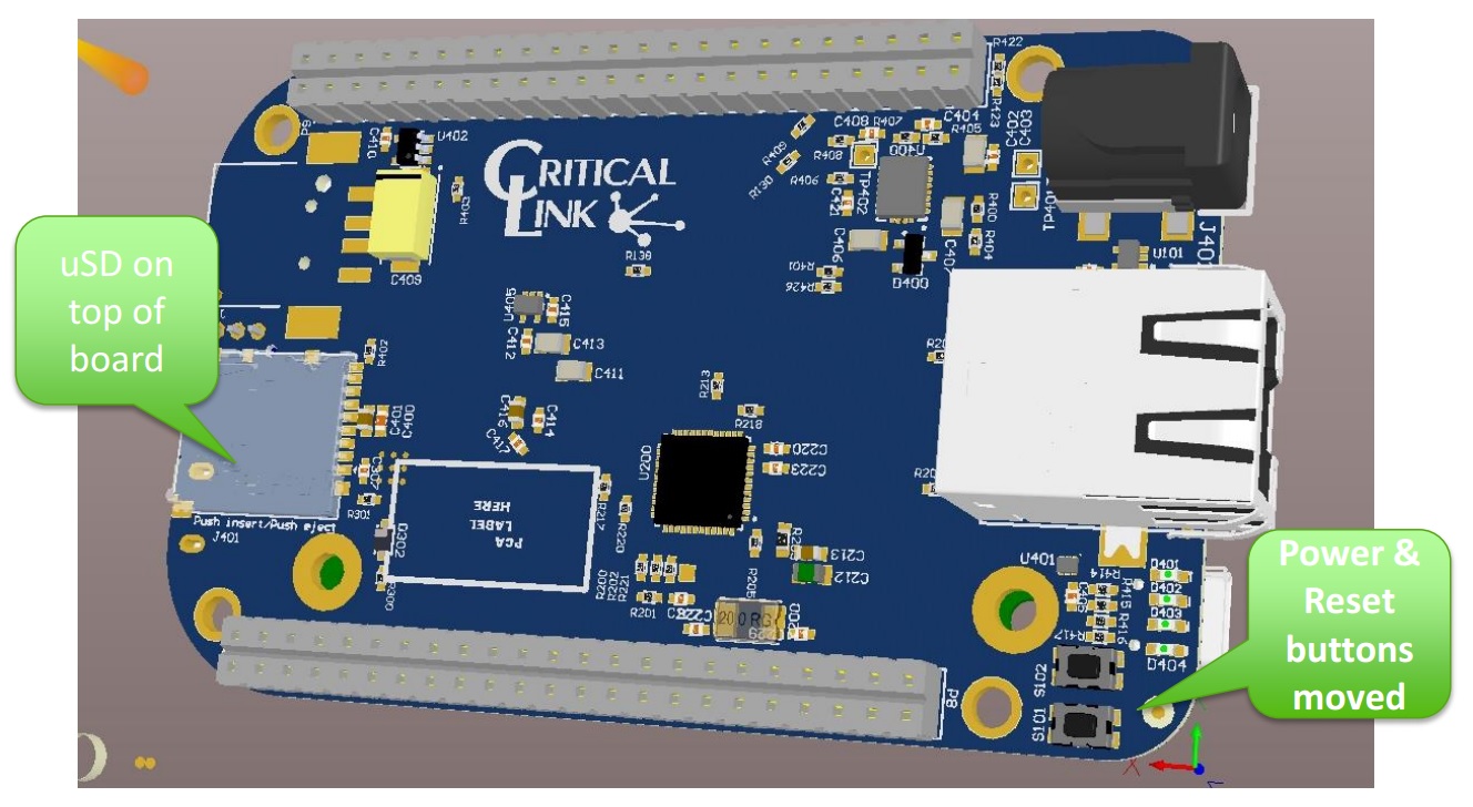
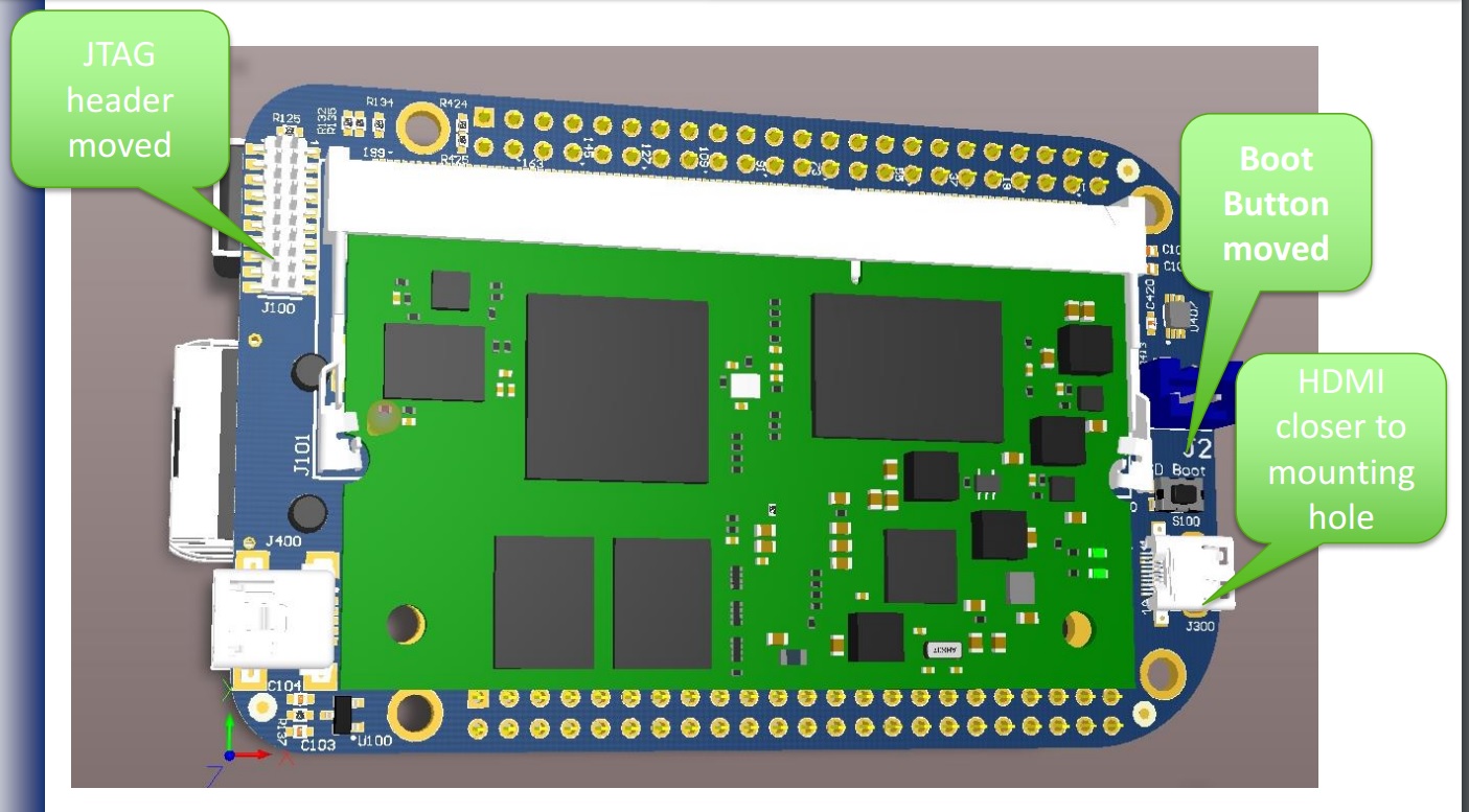
Mechanical
- The MitySOM-335x connector raises the height of one side of the board (opposite the cape headers)
- Power, Reset and Boot buttons have been moved
- HDMI connector moved closer to board edge
- JTAG Header moved
- Debug UART interface is now a 3-pin header (cable included with kit)