Heat Dissipation
THIS IS A WORK IN PROGRESS
This wiki page provides some basic information about the thermal performance of the MitySOM-A5 (revision 1, with engineering silicon). It will capture some basic scenarios using the MitySOM-A5 DevKit, and document various power draw and thermal measurements made in the test.
Summary
| Scen | Heatsink | Airlow | SOM Volt | SOM Cur | SOM Pwr | Amb. Temp | A5 Temp | A5 Rise | Core Cur (1) | DevKit Volt | DevKit Cur | DevKit Pow | Notes |
|---|---|---|---|---|---|---|---|---|---|---|---|---|---|
| 2 | None | N | +12 V | 606 mA | 7.26 W | 24 C | 72 C | 48 C | 11.5 A | 12 v | 0.74 A | 8.89 W | 20 mins after power up |
| 2 | None | Y | +12 V | 24 C | 43 C | 19 C | 20 mins after power up | ||||||
| 2 | Passive 25x25 | N | +12 V | 603 mA | 7.21 W | 24 C | 67 C | 43 C | 11.8 A | 12 | 0.72 A | 8.65 W | 20 mins after power up |
| 2 | Passive 25x25 Spreadfin | N | +12 V | 571 mA | 6.75 W | 24 C | 65 C | 41 C | N/A | N/A | N/A | N/A | 20 mins after power up |
| 2 | Passive 25x25 Spreadfin | Y | +12 V | 516 mA | 6.17 W | 24 C | 37.5 C | 13.5 C | N/A | N/A | N/A | N/A | 20 mins after power up |
| 2 | Passive 25x25 | Y | +12 V | 539 mA | 6.45 W | 24 C | 39 C | 15 C | 10 A | 12 | 0.66 | 7.92 W | 20 mins after power up |
| 2 | Active 23x23 | Y | +12 V | 540 mA | 6.47 W | 25 C | 47 C | 23 C | 10.5 A | 12 V | 0.7 A | 8.4 W | 12 hrs after power up |
| 2 | Active 23x23 | Y | +5 V (2) | 730 mA | 3.56 W | 24 C | 39 C | 15 C | 9.0 A | 12 V | 0.16 A | 1.9 W | 20 mins after power up |
Additional Notes
1. The PM Bus current readout from the power chips appears to have a bias or is impacted by the LDO voltage.
2. To power the SOM at +5V, JP1 resistor was removed and a wire tacked into VIN_MONITOR net on devkit board. UVLO on input switch limits minimum voltage to about 10 V because of PCIe interface. There is a +5V LDO in the core supplies that appears to account for about 1.9 W at +12V input. The DevKit power now represents power not consumed by the SOM.
3. The 'Y' in the 'Airflow' column for the active heatsinks is for the fan on the heatsink, no additional airflow was provided via a desktop fan.
4. The 'SOM Pwr' readings come from the on-module power sensor, the 'DevKit Pow' readings come from an external power supply used to supply power to the DevKit.
Thermal options
No Heatsink, Passive Airflow
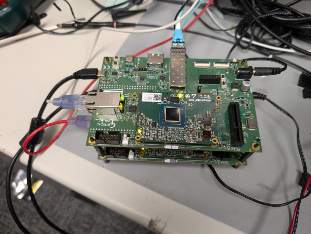
No Heatsink, Forced Airflow
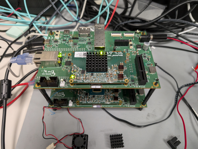
Passive 25x25x8mm heatsink, Passive Airflow
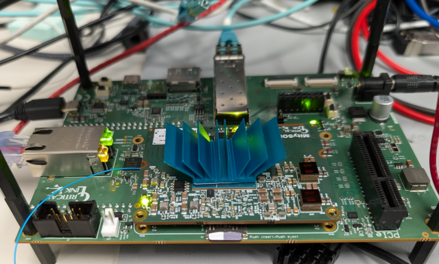
Passive 23x23x14.5mm spreadfind heatsink, Passive Airflow
Passive 25x25x8mm heatsink, Forced Airflow
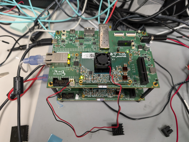
Active 23x23 heatsink with integrated fan
Load Scenarios
Scenario 1: Booted to Uboot
Scenario 2: Boot to linux
In this scenario, the base_project is loaded into the FPGA bitstream and the processor allowed to boot to linux and essentially run IDLE while connected to the network. The board was allowed to run for at least 20 minutes before checking the temperature.
Scenario 3: QSFP+ Packet Test