JTAG Chains
Small Form Factor JTAG Connector
Hirose connector:
- 2 +3.3V power pins
- 2 reset controls
- 5 HPS JTAG
- 9 HPS TRACE
- 4 FPGA JTAG
- 1 debug present
- x GND pins
HPS TRACE MUX Control
The debug adapter includes a pin to indicate when the adapter should take control of the TRACE port instead of routing it to the edge connector fingers. This changes the connections on the SPST MUXes on the module to route the trace lines to the debug header instead of the edge connector.
This is optional on the debug breakout board (some customers will want to use the other peripherals to the HPS where the TRACE pins are located.) This option can be set by a mechanical switch on the breakout adapter.
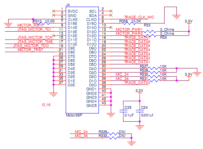
Breakout Adapter
The breakout adapter includes a Mictor connector:
JTAG Chain Options
Customers that don't intend to use the TRACE port may want the JTAG chains combined or separate for different debug purposes. These options are controlled by a mechanical switch.