SSeMMC support for MitySOM AM572x
Added by Sandeep Sivadas about 3 years ago
Hi,
We need to integrate eMMC Flash with MitySOM SOM. Please suggest appropriate Part No: for the same.
What will be the memory size needed for eMMC ?
Thanks and regards
Sandeep S
Replies (3)
JC RE: eMMC support for MitySOM AM572x - Added by Jonathan Cormier about 3 years ago
Sandeep Sivadas wrote:
Hi,
We need to integrate eMMC Flash with MitySOM SOM. Please suggest appropriate Part No: for the same.
What will be the memory size needed for eMMC ?
The memory size depends on how much space you need for your product
For example this one, MTFC64GAPALBH-IT, which comes in a variety of sizes 8GB, 16GB, 32GB, 64GB, 128GB, e.MMC v5.1, 153-ball TFBGA.
https://www.micron.com/products/managed-nand/emmc/part-catalog/mtfc64gapalbh-it
Note this one in particular is industrial temp so may be more expensive than if you only need commercial temp.
Note the 153-ball TFBGA package has a lot of different manufacturers which are pin compatible.
https://www.mouser.com/c/semiconductors/memory-ics/emmc/?package%20%2F%20case=TFBGA-153
SS RE: eMMC support for MitySOM AM572x - Added by Sandeep Sivadas about 3 years ago
Hi Jonathan,
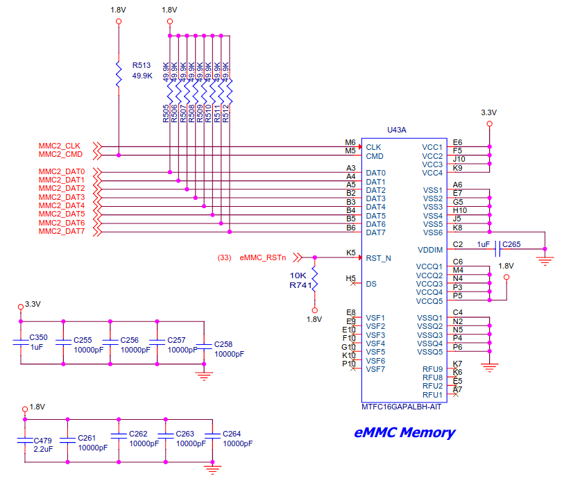
We designed an eMMC circuit using MTFC16GAPALBH-AIT. As per the data sheet of MitySOM MMC2 signals are 1.8V level.
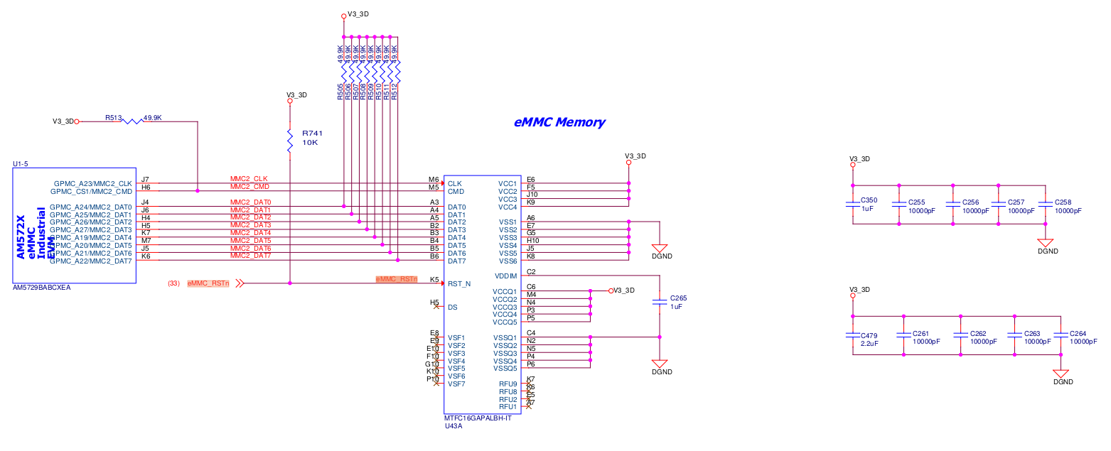
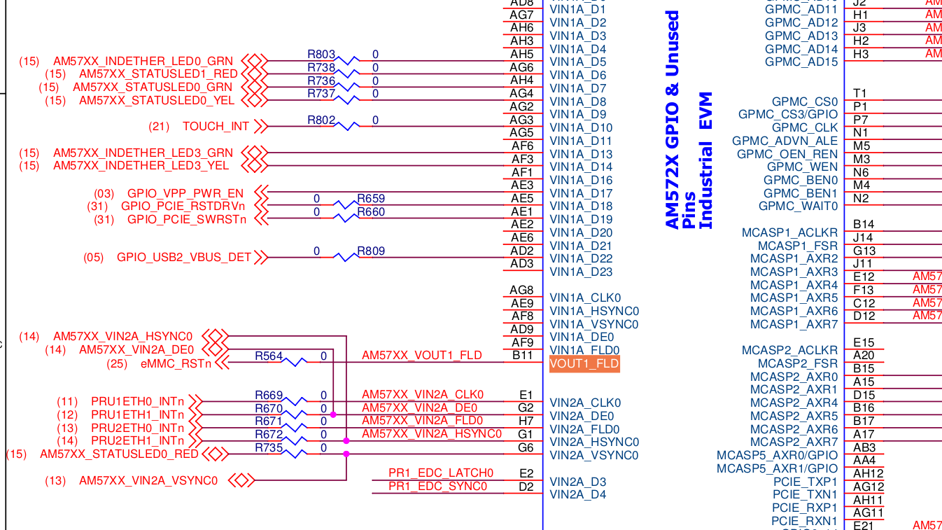
we follow the AM572x-IDK schematic design for designing eMMC circuit. But there an eMMC_RSTn signal is connected with MTFC16GAPALBH-AIT, which is same as AM5729 pin B11.
But in MitySOM AM57x schematic design, B11 pin is J10A 21, and in the MitySOM datasheet B11 pin is SOM's 64 (J1). So which pin we can use as eMMC_RSTn ?
schematic design of eMMC Circuit and the links datasheet link i used for the design.
Here i am attaching the TI AM572x-IDK Schematic design and Our Design file. Can you please verify the circuit.
Thanks and regards
Sandeep S
| Screenshot from 2023-06-07 12-50-07.png (89.4 KB) Screenshot from 2023-06-07 12-50-07.png | Our Design | ||
| Screenshot from 2023-06-07 12-52-05.png (113 KB) Screenshot from 2023-06-07 12-52-05.png | TI-AM572x IDK Design | ||
| Screenshot from 2023-06-07 12-49-23.png (320 KB) Screenshot from 2023-06-07 12-49-23.png | TI-AM572x IDK Design |
JC RE: eMMC support for MitySOM AM572x - Added by Jonathan Cormier about 3 years ago
Per this e2e post, it should be okay to use 1.8V signal levels with an eMMC.
https://e2e.ti.com/support/processors-group/processors/f/processors-forum/827480/am5718-emmc-at-1-8v
The eMMC_RSTn signal can be connected to any gpio on the SOM or left floating. By default, eMMC disable the reset signal so it has to be explicitly enabled if its usage is important to you.
Per the datasheet: https://www.mouser.com/datasheet/2/671/micron_technology_mict-s-a0006806196-1-1759129.pdf
Reset: The RST_n signal is used by the host for resetting the device, moving the device to the pre-
idle state. By default, the RST_n signal is temporarily disabled in the device. The host must set ECSD
register byte 162, bits[1:0] to 0x1 to enable this functionality before the host can use it.
If host does not use H/W RESET (RST_n), pull-up resistance is not needed on RST_n line (Extended_CSD162 = 00h).
Note: Be careful to avoid connecting to any of the RFU pins when doing the layout. You can use the NC pins for escape routing but the RFU pins may be used in future eMMC versions which could mean your product cannot easily switch to the newer design when the current one goes obsolete.