Bootloader Overview
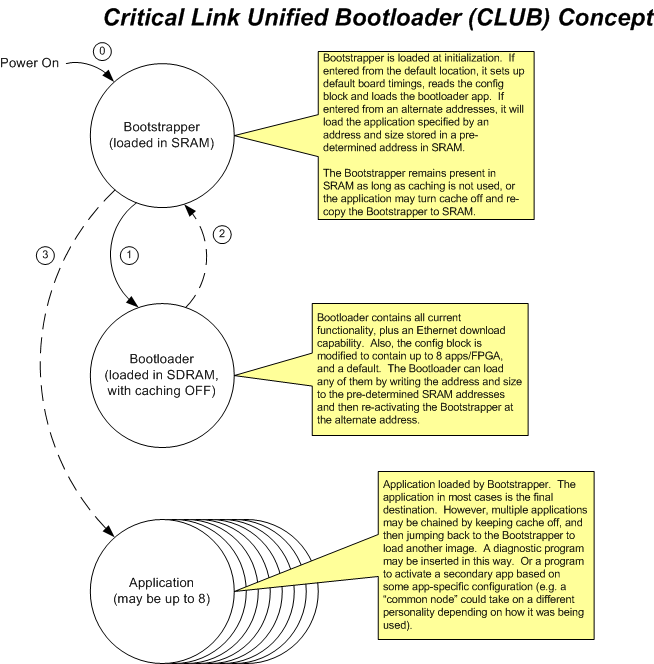
The figure below outlines the basic boot sequence. The boot sequence involves the following 5 images: the bootstrapper image, the bootloader DSP image, the bootloader FPGA image, the Application DSP image, and the Application FPGA image.
bootstrapper
The Bootstrapper is a nearly trivial application, which is copied from a known address in FLASH (offset 0) to SRAM and then executed. The tasks performed by the Bootstrapper require no external communication. The Bootstrapper provides two entry points. The default entry point (address “zero”, as jumped to at power up) will cause the Bootstrapper to set-up all required MityDSP board timings in a “least common denominator” state (memory timing, CPU and EMIF clock slow enough for use with any of the MityDSP variants), and load the Bootloader software from a pre-determined location and size.
If activated from the alternate entry point, the Bootstrapper will not modify any MityDSP timing information. It will look to four reserved locations in its memory space… software image location and size, and FPGA image location and size. If the FPGA size is non-zero, it will program the specified image to the FPGA. The Bootstrapper will copy the software image from FLASH to SDRAM, and then set up the initial stack pointer and jump to the start of the new program.
The four reserved addresses must be at static, predetermined locations in SRAM, so the Bootloader (or other applications) know where to write location and size information.
bootloader
The Bootloader application picks up from where the Bootstrapper left off. The Bootloader is a C++ application, making full use of the MityDSP common libraries and DSP/BIOS™ operating system. he Bootloader may install the various firmware device handlers in the normal manner. This will include at least the two serial port drivers. If the Ethernet core is available in the Bootloader FPGA and the board configuration block has a non-zero MAC address, the Ethernet driver and LWIP stack will be initialized (initially with an address derived from the board serial number on the “0.0.0.0/24” network). Once the stack is running, the Bootloader will UDP broadcast an “I’m Alive” message (0xB00E1E10) on port 56789 once per second.
Note that the location of I/O pins required for Ethernet is (mostly) standardized in the MityDSP hardware, but their presence is not guaranteed on all I/O board implementations. The short-term solution is to provide a Bootloader FPGA image without Ethernet support as the default. The longer-term solution is to develop FPGA code to tri-state the I/O pins used by the Ethernet until the device is enabled. The Bootloader will only enable the device if it finds the firmware Ethernet core present, and if the board configuration contains a non-zero MAC address.
The bootloader will accept commands over either of the serial ports, as well as over UDP port 56789.
Go to top

