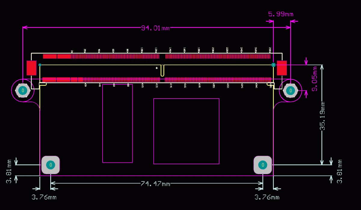
Mounting Hole Locations for Carrier Boards
Shown below is an image of the JAE 314-Pin connector (Manufacturer Part Number MM70-314-310B1-1-R300) for use with the MitySOM-5CSx line of System on Modules as well as the module outline with mounting hole locations (white).
Altium Designer Schematic and Footprint library files of the module connector can be found on this wiki page (https://support.criticallink.com/redmine/projects/mityarm-5cs/wiki/CAD_Files_and_Information) as well as a 3D step model of the module.
The pink/purple dimensions and outline show the mounting hole locations if the Critical Link MitySOM-5CSx heat-spreader is to be utilized or other heat dissipation device. Note that the mounting hole diameters for the heat spreader and module are both 3.175mm (shown in this wiki page for the dev board https://support.criticallink.com/redmine/projects/5csxbase/wiki/Baseboard_Mounting_Hole_Information).
The dimensions are all taken from the center of the larger (right side) orientation pin of the JAE connector footprint.

Mounting hardware options
The module mounting holes are 3.175mm in diameter and Critical Link typically uses 4-40 Screws (3/8" long) with 4-40 standoff (1/8" high) and 4-40 Thumb Nuts (all stainless steel).
We order these items from McMaster-Carr but any similar screws, standoffs or nuts will suffice.
Standoff: McMaster Carr PN - 91115A510 (Replacement 91115A160)
Screw: McMaster Carr PN - 95345A432
Thumb nut: McMaster Carr PN - 95150A120
Go to top

