B2521 Raw Order and Pixel Packing (Normal Modes)
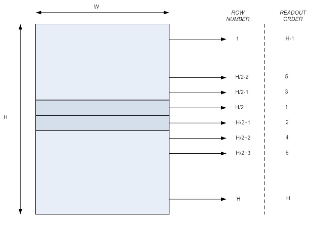
In order to achieve maximum frame rates, the MityCAM-B3521F camera shall readout the CIS2521 sensor using both the top and bottom half sensor outputs starting from the center of the sensor towards the top/bottom as illustrated below.

Within a row, data is transmitted left to right according to Table 1 and Table 2 below, where P0 is the left most pixel in the region of interest.
Table 1 16 Bits Per Pixel Camera Link Tap Assignments
| CamLink Clock | 8-Bit Camera Link Tap | |||||||||
| J | I | H | G | F | E | D | C | B | A | |
| 0 | P4 MSB | P4 LSB | P3 MSB | P3 LSB | P2 MSB | P2 LSB | P1 MSB | P1 LSB | P0 MSB | P0 LSB |
| 1 | P9 MSB | P9 LSB | P8 MSB | P8 LSB | P7 MSB | P7 LSB | P6 MSB | P6 LSB | P5 MSB | P5 LSB |
| 2 | P14 MSB | P14 LSB | P13 MSB | P13 LSB | P12 MSB | P12 LSB | P11 MSB | P11 LS | P9 MSB | P9 LSB |
…
Table 2 8 Bits Per Pixel Camera Link Tap Assignments
| CamLink Clock | 8-Bit Camera Link Tap | |||||||||
| J | I | H | G | F | E | D | C | B | A | |
| 0 | P9 | P8 | P7 | P6 | P5 | P4 | P3 | P2 | P1 | P0 |
| 1 | P19 | P18 | P17 | P16 | P15 | P14 | P13 | P12 | P11 | P10 |
| 2 | P29 | P28 | P27 | P26 | P25 | P24 | P23 | P22 | P21 | P20 |
…
B2521 Raw Order and Pixel Packing (Psuedo Single Port)
The latest B2521 firmware supports psuedo single port operation, which presents data to the camera link interface in raster order instead of the row order mentioned above. This mode is only supported in rolling shutter and the frame rate is limited to 1/2 the maximum frame rate on the camera. See the MityCAM-B2521 User's Guide for more information about configuration of this mode.
Go to top

