Forums » Software Development »
I2C Bus
Added by Bruce Kenny over 12 years ago
We are currently investigating a problem accessing the I2C0 bus.
My initial enquiry is to find out what devices are on the MityDSP SOM to insure we are not conflicting.
Our SOM is a L138-DX-225-RI. We are using uBoot to boot the device but thereafter are using our own software (i.e. not Linux).
Our problem is that we do several transmits and receives on the I2C but occasionally we get begin to get I2C errors (bus arbitration, Nacks) that, once they occur, persistently happen.
Thanks
Bruce Kenny
Replies (7)
RE: I2C Bus - Added by Michael Williamson over 12 years ago
Hi Bruce,
I believe that the I2C addresses for I2C0 are described in the Carrier Board Design Guide.
From section 3.3.8:
All modules include support for up to 2 Inter-Integrated Circuit (I2C) ports. I2C0 is connected to an on-board
prom (address 1010XXXb) that is used to hold factory configuration data (serial number, MAC address, etc.) and
is therefore dedicated to this function. I2C0 is also connected to an on-board Power Management Integrated
Circuit (PMIC), the TPS65023 (address 1001000b). Users may use the I2C0 port however, to interface to other
devices having different addresses than those mentioned on this bus. The I2C ports share pins with other
peripherals on the SOC processor. Refer to the SOC datasheet for more details.
-Mike
RE: I2C Bus - Added by Ed Smith over 12 years ago
I'm working with Bruce on this issue. It would be really helpful to have the part numbers of the other devices, particularly the PROM, and a schematic of the I2C portion of the circuit on the module.
Thanks
Ed Smith
RE: I2C Bus - Added by Michael Williamson over 12 years ago
The PMIC is TPS65023RSBT. The PROM is 24AA02-I/MS. Pins 1, 2, and 3, of the PROM are no-connects.
The I2C0_SCL and I2C0_SDA lines each have pullups (4.7K) to +3.3V.
Do you have scope traces of the I2C lines when this condition occurs?
-Mike
RE: I2C Bus - Added by Ed Smith over 12 years ago
Thanks for the swift response. That is exactly the info I've been looking for.
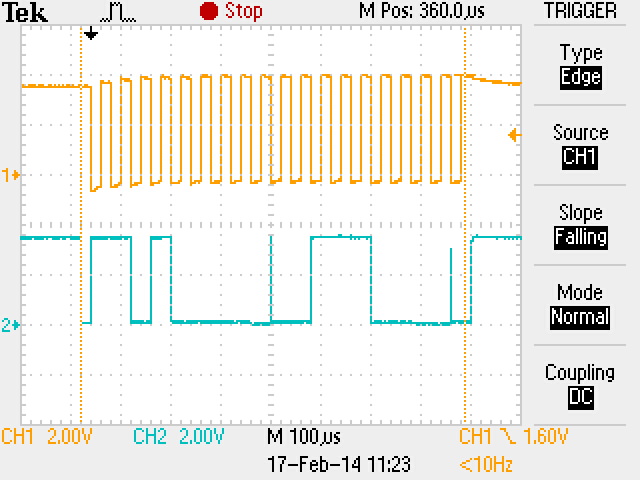
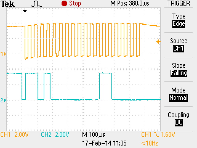
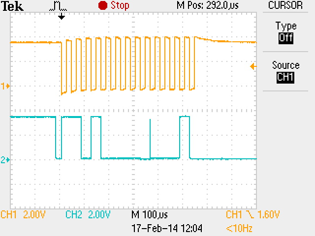
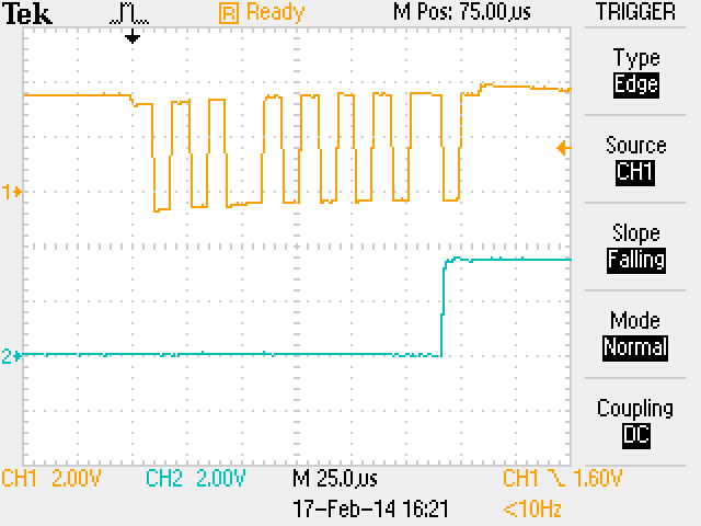
I have attached some waveforms. The first is normal operation. The second shows the bus hanging at the end of the access. The third shows the master terminating the access, presumably as it has detected a bit error and thinks there is another master on the bus. The final shot shows the process we have employed to recover from the hang. Basically toggling the clock up and down until who ever is holding on to the bus releases.
We have a pull up on each line of 2k2. Total combined pull up I measured at 1K3. Rise time is 370ns. Clock speed is 25KHz. We have two other devices on the bus. An ADC device MCP3426 and ETI device DS1682.
Ed Smith
RE: I2C Bus - Added by Michael Williamson over 12 years ago
I don't like the glitches in your "noramal operation" or "early termination" scope plots. Those should not be there.
I am looking at the datasheets for the MCP3426 and the DS1682.
Both appear to have the potential for the I2C slave address. Any chance this is the case?
MCP3426 says it's address is 1101XXX, where the bottom three bits are factory programmed. What is yours set to?
DS1682 says it's address is 1101011. Possible there is contention?
Do you have issues addressing the factory configuration EEPROM during bootup? E.G., if you break into u-Boot and run "factoryconfig" do you get valid data?
Do any of those parts attempt clock stretching? The I2C interface on the L138 does not support clock stretching. Is the recovery toggleing not periodic because of the software?
-Mike
RE: I2C Bus - Added by Ed Smith over 12 years ago
Thank you for your comments.
The glitches you can see on the waveforms occur when there is an acknowledge bit. The master stops driving and the slave starts. If they occurred on the clock line or during the high period of the clock I would be more suspicious.
The address for the MCP3426 has a factory set address. The one we have is set to 1101000 so I don't think there is a contention.
The EEPROM appears to be working correctly on most of our boards. We have had problems with that on one board but we think that is a separate issue and have put that aside.
I can't see any clock stretching occurring when either of our devices are accessed as you can see from the screenshots. There are some very funny waveforms produced when the module boots though. Sometimes the clock is low for quite long periods.
I didn't quite understand your last question, "Is the recovery toggling not periodic because of the software?". Could you explain further?
I'm currently looking at the power feed to the module in terms of level and transients to see if there is a system cause. The module does appear to be very sensitive to level. If the supply rail is more than about 100mV below nominal the boot sequence can repeat over and over. Any thoughts?
Ed Smith

