LVDS transceiver for 1000Mb Ethernet MAC & 1000Base-X problem
Added by Charles Garcia over 10 years ago
Hi,
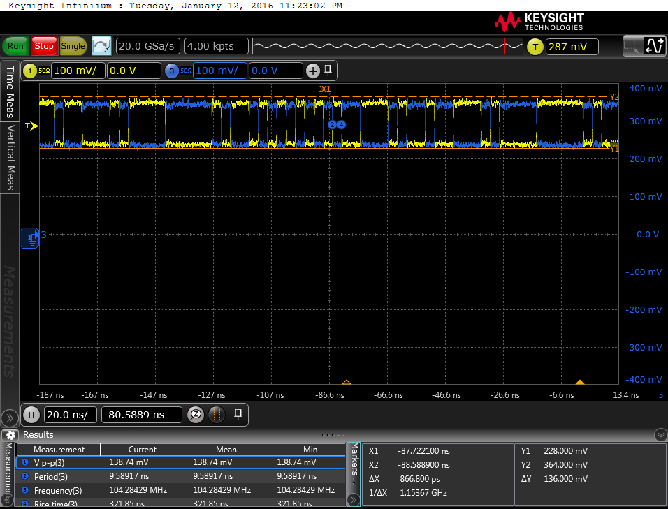
I have been attempting to use the development kit to setup and implement a system which interfaces to an externally connected SFP module which I have connected via the SPIe connection to the dev board. I instantiated the TSE Ethernet core from Altera together with the pcs phy 1000Base x transceiver interface. All built well, however when I inspected the differential signals from the GXB io, the signal voltage levels look wrong. I can see my Ethernet packets being generated on the GXB Tx lines, however the common mode voltage is only 300mv and the differential voltage is only 270mv (signals measured using scope with a differential interface). I tried to vary the VoD setting to 1 or 2 in the qsf file however the fitter through a fit..
- is there a setting that I am missing?
- could I have somehow damaged the I0BANK_B0L or I0BANK_B1L banks (I have tried both)
- do I need to implement the dynamic transceiver configuration (yuck!!)
Thanks guys…
| diff output.png (103 KB) diff output.png |
Replies (1)
RE: LVDS transceiver for 1000Mb Ethernet MAC & 1000Base-X problem - Added by Adam Dziedzic over 10 years ago
Hi Charles,
The GXB TX details can be found in Altera's documentation:
https://www.altera.com/content/dam/altera-www/global/en_US/pdfs/literature/hb/cyclone-v/cv_5v3.pdf
Are you using the on-chip biasing network and termination, or external termination?
Because the transmitter is a current mode output, it needs to have either the internal or external termination to create the differential voltage. As long as there is a reasonable termination network, the VCM should be 0.65V. It sounds like you are using the PCI Express connector for the GXB interface. These TX pairs are AC coupled on the Dev Board, so I assume you are using the on-chip biasing circuitry. Does the VCM and VOD look any better at the MitySOM side of the AC coupling caps on the bottom of the Dev Board (C208/C209)?
With the AC coupled link, the receiving end of the TX pair can run a different VCM than the Cyclone V GXB generates through the internal biasing network. That VCM depends on another set of termination resistors.
Programmable Transmitter VCM

The transmitter buffers have on-chip biasing circuitry to establish the required VCM at the transmitter
output. The circuitry supports a VCM setting of 0.65 V.

Note: On-chip biasing circuitry is available only if you select one of the Termination logic options in
order to configure OCT. If you select external termination, you must implement off-chip biasing
circuitry to establish the VCM at the transmitter output buffer.

Programmable Transmitter Differential OCT

The transmitter buffers support optional differential OCT resistances of 85, 100, 120, and 150 Ω . The
resistance is adjusted by the on-chip calibration circuit during calibration, which compensates for PVT
changes. The transmitter buffers are current mode drivers. Therefore, the resultant VOD is a function of
the transmitter termination value.
The waveform you posted does not look distorted, so the GXB outputs appear to be functioning fine. And I don't see any reason you would need dynamic transceiver configuration.
Hope this helps,
- Adam

