Using spidev
Objective
The objective of this wiki page is to provide information about setting up a spi device, how to access it from Linux user-space using spidev, and how to verify that it is working.
Information
The SPI4 bus is accessible via the J5 expansion header:
| Pin function | ARM ball | Devkit connector |
| SPI4_SCLK | N7 | J5-12 on devkit |
| SPI4_D1 | R4 | J5-13 on devkit |
| SPI4_D0 | N9 | J5-10 on devkit |
| SPI4_CS0 | P9 | J5-8 on devkit |
Configuring SPI4 on the devkit
- U-boot: Make the following changes in order to set up the spi4 pinmux on these pins
Note: If you have a non-fpga SOM, then you'll need to update the core_padconf_array_essential_mitysom_nonfpga_devkit array instead.
Note: The spi clk must be muxed as an input or you won't receive any data on the miso--- a/board/cl/mitysom-57x/mux_data.h +++ b/board/cl/mitysom-57x/mux_data.h @@ -37,10 +37,10 @@ static const struct pad_conf_entry core_padconf_array_essential_mitysom_devkit[] {GPMC_A5, (M7 | PIN_INPUT)}, /* R9 gpmc_a5.i2c5_sda */ {GPMC_A6, (M14 | PIN_INPUT_PULLDOWN)}, /* R5 gpmc_a6.gpio1_28 J5.15 */ {GPMC_A7, (M14 | PIN_INPUT_PULLDOWN)}, /* P5 gpmc_a7.gpio1_29 J5.5 */ - {GPMC_A8, (M14 | PIN_INPUT_PULLDOWN)}, /* N7 gpmc_a8.gpio1_30 J5.12 */ - {GPMC_A9, (M14 | PIN_INPUT_PULLDOWN)}, /* R4 gpmc_a9.gpio1_31 J5.13 */ - {GPMC_A10, (M14 | PIN_INPUT_PULLDOWN)}, /* N9 gpmc_a10.gpio2_0 J5.10 */ - {GPMC_A11, (M14 | PIN_INPUT_PULLDOWN)}, /* P9 gpmc_a11.gpio2_1 J5.8 */ + {GPMC_A8, (M8 | PIN_INPUT)}, /* N7 gpmc_a8.spi4_sclk J5.12 */ + {GPMC_A9, (M8 | PIN_INPUT)}, /* R4 gpmc_a9.spi4_d1 J5.13 */ + {GPMC_A10, (M8 | PIN_OUTPUT)}, /* N9 gpmc_a10.spi4_d0 J5.10 */ + {GPMC_A11, (M8 | PIN_OUTPUT)}, /* P9 gpmc_a11.spi4_cs0 J5.8 */ {GPMC_A12, (M14 | PIN_INPUT_PULLDOWN)}, /* P4 gpmc_a12.gpio2_2 J11.8 */ {GPMC_A13, (M1 | PIN_INPUT | MANUAL_MODE)}, /* R3 gpmc_a13.qspi1_rtclk */ {GPMC_A14, (M1 | PIN_INPUT | MANUAL_MODE)}, /* T2 gpmc_a14.qspi1_d3 */
- Kernel: Add the mcspi4 node and add a single spidev device at chipselect 0
--- a/arch/arm/boot/dts/am57xx-mitysom-baseboard.dts
+++ b/arch/arm/boot/dts/am57xx-mitysom-baseboard.dts
@@ -22,3 +22,16 @@
 &uart10 {
        status = "okay";
 };
+
+&mcspi4 {
+       status = "okay";
+       pinctrl-names = "default";
+       ti,pindir-d0-out-d1-in=<1>;
+
+       spidev@0 {
+               compatible = "spidev";
+               spi-max-frequency = <1000000>;
+               reg = <0>; # cs0
+               status = "okay";
+       };
+};
- Kernel: Build the linux spidev_test executable and copy to devkit:
 $ make O="build-mitysom57x" -C tools/spi/
 $ scp build-mitysom57x/spidev_test root@eth:
Connect logic analyzer or oscilloscope:
Run spidev_test
root@mitysom-am57x:~# ./spidev_test -D /dev/spidev1.0 -v
spi mode: 0x0
bits per word: 8
max speed: 500000 Hz (500 KHz)
TX | FF FF FF FF FF FF 40 00 00 00 00 95 FF FF FF FF FF FF FF FF FF FF FF FF FF FF FF FF FF FF F0 0D | ......@......................ð.
RX | 00 00 00 00 00 00 00 00 00 00 00 00 00 00 00 00 00 00 00 00 00 00 00 00 00 00 00 00 00 00 00 00 | ................................
Spi signals seen on spi4_sclk and spi4_d0
Note: spidev_test is just to send some signal over the spi bus to make sure the pinmux and kernel config is in place. See the libdaq repo for same userspace drivers that use spidev.
Troubleshooting
Verify pinmux change in u-boot was done correctly
We can use a memory tool to print out the pinmux register and make sure it is set to the value we expect.
- Open the TRM and search for CTRL_CORE_PAD_GPMC_A8
https://www.ti.com/lit/ug/spruhz6l/spruhz6l.pdf page 4226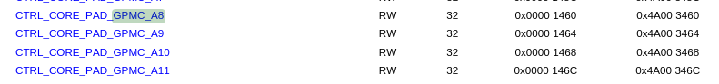
We see that the pinmux memory addresses for GPMC_A8 through GPMC_A11 is 0x4A003460 through 0x4A00346C - On the devkit, we can use devmem2 to print the register values.
root@mitysom-am57x:~# devmem2 0x4A003460
/dev/mem opened.
Memory mapped at address 0xb6f2b000.
Read at address  0x4A003460 (0xb6f2b460): 0x00050008
root@mitysom-am57x:~# devmem2 0x4A003464
/dev/mem opened.
Memory mapped at address 0xb6fa9000.
Read at address  0x4A003464 (0xb6fa9464): 0x00050008
root@mitysom-am57x:~# devmem2 0x4A003468
/dev/mem opened.
Memory mapped at address 0xb6fc0000.
Read at address  0x4A003468 (0xb6fc0468): 0x00010008
root@mitysom-am57x:~# devmem2 0x4A00346C
/dev/mem opened.
Memory mapped at address 0xb6f09000.
Read at address  0x4A00346C (0xb6f0946c): 0x00010008
- In the TRM, you can jump to the CTRL_CORE_PAD_GPMC_A8 section to decode the values read from the register. In this case the most important byte is the LSB, which is 8 which selects the spi4 mode.
If the pinmux values don't match what you expect, verify the changes in u-boot and that it was built properly and the correct version was copied to the devkit sd card.
libdaq
For an example userpace library, see libdaq dac8554.cpp
Go to top

