JTAG Debug Interface
The JTAG (J2) interface is located on the SOM and requires an debug adapter board. The board will contain a TI14 connector (J2) for the ARM and DSP and a Xilinx 14-pin connector (J3) for the FPGA.
Non-fpga modules
Note: AM57x non-FPGA SOMs have a cTI 20-pin connector instead. The JTAG emulator is plugged into this without the above "debug adapter board".
There is a known issue with the Rev1/2 hardware. Pins 4(TDIS) and 8(GND) need to be shorted for the debugger to attach. These are across the key.
https://software-dl.ti.com/ccs/esd/documents/xdsdebugprobes/emu_xds_target_connection_guide.html#tdis-considerations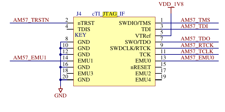
Support JTAG emulators
ARM: TI XDS200 $295, TI XDS110 $99, Blackhawk XDS560 v2 $995
FPGA: Platform Cable USB II, Digilent HS-2 Cable
ARM/DSP debugging
Reference:
http://software-dl.ti.com/processor-sdk-linux/esd/docs/06_03_00_106/linux/How_to_Guides/Hardware_Setup_with_CCS/AM572x_GP_EVM_Hardware_Setup.html#ccs-setup
Note: For booting ARM over JTAG, see the above link and search for Connect without a SD card boot image. You will need to populate JP7 "Powerhold On" as well.
https://www.ti.com/lit/an/sprac17b/sprac17b.pdf
Requires: Code Composer (CCS) v7+
Instructions tested on CCS v10.1 with XDS200 emulator
These instructions assume the board is booted via u-boot and as such ARM clocks and DDR settings are already setup.
- Connect debugger to computer and board
- Open Code Composer (CCS)
- File -> New -> Target Configuration File
- File name: AM5728_XDS200.ccxml
- Check "Use shared location"
- Click Finish
- Edit opened Target Configuration
- Connection: Select the correct debug probe.
"Texas Instruments XDS2xx USB Debug Probe" for the XDS200 - Board or Device: AM5728
- Select Save
- Select Test Connection
xds200_debug_test_connection.log
- Connection: Select the correct debug probe.
- View -> Target Configurations
- In the Target Configuration view, expand the "User Defined folder"
- Right click on the new Target Configuration File and select the "Launch Selected Configuration"
- If a firmware update warning window opens, select Update
If you get an error during update, try updating manually: https://software-dl.ti.com/ccs/esd/documents/xdsdebugprobes/emu_xds200.html#updating-the-firmware
- Open Target Status view, this shows each of the slave cores Power, Clocks, and reset status
- View -> Other, Select Debug/Target Status and Open
- Connect to CortexA15_1
- Right click on CortexA15_1 and select "Connect to target"
- Make sure to resume the core before too long or Linux will get a bit angry, Run -> Resume
- Enable other cores TODO: Not working
- Ensure CortexA15_1 is selected
- In the GEL Files view (usually in bottom right), Select the GEL files category
- Right click in the empty space under "Script | Status", and select "Load GEL..."
- Open the following file which contains the scripts to enable the different cores: C:\ti\ccs1010\ccs\ccs_base\emulation\boards\am572x\gel\AM572x_multicore_reset.gel
- With the CortexA15_1 suspended, select Scripts -> "AM57x Multicore Intialization" -> "AM572x_MULTICORE_EnableAllCores"
- View physical memory addresses
- View -> Memory Browser
FPGA debugging
WIP (TODO)
- Connect debugger to computer and board

Go to top

