- Table of contents
- Example Projects
Example Projects
This page contains information for example FPGA projects for the MitySOM-AM57X Development kit.
All of the development kit reference projects and utilities are available on the mitysom-am57x-ref git repository.
You can use the web link to download a tarball of the reference project, or you can use the git source code management utility (recommended).
The git command line to fetch the files is shown below:
user@linux # git clone git://support.criticallink.com/home/git/mitysom-am57x-ref.git -b main
The main branch currently supports vivado_2019.2. You must install the correct version of Vivado to use the corresponding branch. While possible, using a different version of Vivado for a given branch will not be supported by Critical Link. As new versions of Vivado are released, a news branches will be created for the specific version and published to the site. The reference projects will be updated to ensure proper operation with the release. Not every version of Vivado may be supported. To checkout a specific branch:
user@linux # cd mitysom-am57x-ref
user@linux # git checkout -b main origin/main
Once the branch is checked out, you will see the following repository contents:
.
├── README.md
└── fpga
    ├── devkit_basic_gpio        # project files for DevKit FPGA
    │   ├── README.md
    │   ├── ip                   # Xilinx IP files needed for project
    │   ├── script               # TCL scripts for generating Project or building bitstreams
    │   ├── src
    │   │   ├── constraints      # Xilinx Constraints Files
    │   │   └── hdl              # Project specific source VHDL or Verilog Files
    ├── devkit_project_2
    ├── devkit_project_3
    ├── ...
    └── ip                       # Critical Link Supplied IP used on multiple projects
        ├── common
        ├── gpio
        ├── gpmc
        ├── ip_module_3
        └── ...
MitySOM-AM57X DevKit Basic GPIO Reference Project
A basic reference image for the MitySOM-AM57X FPGA supporting the development kit can be found in the subfolder mitysom-am57x-ref/fpga/devkit_basic_gpio. Within each project folder, a README.md file exists that documents what the project does and how to build it.
user@linux # cd fpga/devkit_basic_gpio
This particular project provides the following main functions:
- A simple slave Block RAM connected via the PCIe bus between the AM5728 and the FPGA
- A simple register based interface using the General Purpose Memory Controller (GPMC) of the AM5728 and the FPGA
- Basic GPIO access to all of the FPGA pins routed from the SOM to the DevKit FPGA Mezzanine Connector (FMC)
- A simulated 60 Hz 1920x1080 video pattern fed to the AM5728 24 bit video input port
This is represented by the attached block diagram:
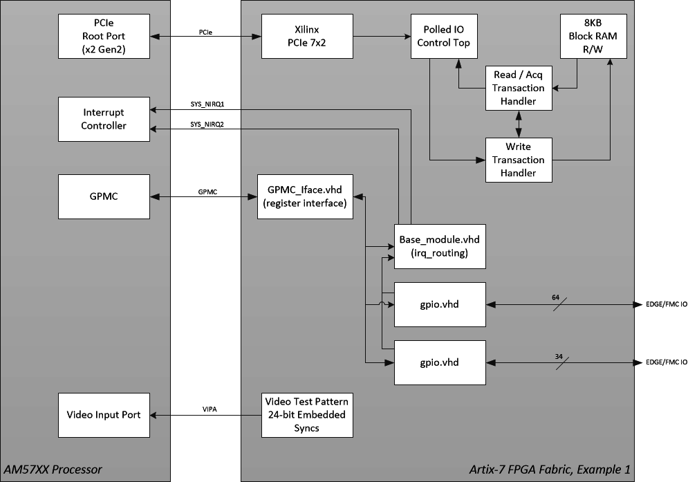
This project should include all of the necessary pin constraints / mapping information to start a new project with customer specific requirements as well as learn to compile and load a bitstream onto the devkit.
Creating a Vivado Project (GUI / Project Mode)
To create a Vivado project to support running vivado, run the following TCL script to build the project.
user@linux # vivado -mode batch -source script/gen_devkit_project.tcl
This will create a project at ./devkit/devkit.xpr, using external references for the provided source files. You can open this file using the Vivado GUI program.
Building the project from the Command line.
To create a bitstream running vivado in non-project mode, run the following TCL script to build the project.
user@linux # vivado -mode tcl -source ./script/build_devkit_bitstream_batch.tcl
This will create an output folder ./devkit_output and will place the build report files as well as a generated bitstream.
Running the demonstration
Once you have compiled the bitstream and generated a binary file for uBoot, upload the binary file to the FAT / boot partition on the SD card. On the devkit, you can remove the SD card and plug it into your PC and copy the file over. Or, you can use secure copy (scp) to transfer the file over a connected network interface:
user@host:devkit_base_gpio$ scp devkit_output/fpga_7a15t.bin root@target.ip.address:/boot/fpga_7a15t.bin
Once the FPGA binary is installed, reboot the unit and stop in the uBoot bootloader prompt. Issue the following commands to load the binary into RAM and transfer the bitstream onto the FPGA. Note: The stock devkit may already provide uBoot scripts to perform this operation; this is detailed in the Programming the FPGA Through U-Boot page.
=> load mmc 0 0x82000000 fpga_7a15t.bin
=> fpga load 0 0x82000000 ${filesize}
While in the bootloader, it is possible to interrogate registers available on the GPMC bus using the memory modify and memory dump commands. Once you are ready to boot into linux, you can resume the boot sequence by executing the bootcmd environment script, as shown. Note: The stock devkit environment may do this automatically.
=> run bootcmd
Accessing the GPMC / Reading the base_module.vhd version register
The reference project along with most of our fpga projects contains the base_module.vhd which is responsible for interrupt routing. It also includes a version register that can be read.
The documentation for this module can be found in the mitysom-am57x-ref project. And the kernel driver code which parses this version register can be found in the irq-mitysom-am57x-fpga.c driver
For demonstration purposes, we can read the version by reading the top of the gpmc register space. The register returns a cycling value that repeats every four reads, see above documentation for details.
root@mitysom-am57x:~# memtool 0x01000000 1
Reading 0x1 count starting at address 0x01000000

0x01000000:  00000000

root@mitysom-am57x:~# memtool 0x01000000 1
Reading 0x1 count starting at address 0x01000000

0x01000000:  00005530

root@mitysom-am57x:~# memtool 0x01000000 1
Reading 0x1 count starting at address 0x01000000

0x01000000:  00008B0C

root@mitysom-am57x:~# memtool 0x01000000 1
Reading 0x1 count starting at address 0x01000000

0x01000000:  0000C000
As an example, we can extract the year from the 2nd register read, and the month/day from the 3rd register read
root@mitysom-am57x:~# # Convert hex to decimal
root@mitysom-am57x:~# num=$((16#00005530))
root@mitysom-am57x:~# # Extract year from bits 12:8
root@mitysom-am57x:~# echo $(( (num >> 8 & 0x1F) + 2000 ))
2021
root@mitysom-am57x:~# num=$((16#00008B0C))
root@mitysom-am57x:~# # Extract month from bits 11:8
root@mitysom-am57x:~# echo $(( (num >> 8 & 0xF) ))
11
root@mitysom-am57x:~# # Extract day from bits 4:0
root@mitysom-am57x:~# echo $(( (num & 0x1F) ))
12
Accessing the GPMC / GPIO modules
The reference project connects two simple GPIO modules to the GPMC bus using the provided GPMC_Iface.vhd module. The GPIO modules provide read/write control over all of the FPGA IO on the SOM that is connected to the FMC connector on the DevKit. Critical Link provides a linux driver for these GPIO blocks. If they are compiled as modules you may need to load them:
root@mitysom-am57x:~ # modprobe gpio-mitysom-am57x-fpga
Once the modules are loaded, you should be able to control the state of all of the FMC IO pins using the linux gpio sysfs framework. To get a mapping of each linux GPIO number to the devkit schematic net name, simply run:
root@mitysom-am57x:~# cat /sys/kernel/debug/gpio
Accessing the PCIe 8KB Block RAM
There is no driver provided to control the PCIe 8KB block RAM, as all it is in the example is an externally accessing memory buffer. In order to access the PCIe 8KB block ram, you must enable the PCIe end-point. After it is enabled, tools such as devmem2 or simple applications using /dev/mem can be used to peek and poke the memory.
First, verify that the PCIe endpoint was correctly detected and initialized:
root@mitysom-am57x:~# lspci -v
00:00.0 PCI bridge: Texas Instruments Multicore DSP+ARM KeyStone II SOC (rev 01) (prog-if 00 [Normal decode])
        Flags: bus master, fast devsel, latency 0, IRQ 174
        Memory at 20100000 (64-bit, non-prefetchable) [size=1M]
        Bus: primary=00, secondary=01, subordinate=ff, sec-latency=0
        I/O behind bridge: None
        Memory behind bridge: 20200000-202fffff [size=1M]
        Prefetchable memory behind bridge: None
        Capabilities: [40] Power Management version 3
        Capabilities: [50] MSI: Enable+ Count=1/1 Maskable- 64bit+
        Capabilities: [70] Express Root Port (Slot-), MSI 00
        Capabilities: [100] Advanced Error Reporting
        Kernel driver in use: pcieport
lspci: Unable to load libkmod resources: error -12

01:00.0 Memory controller: Xilinx Corporation Device 7022
        Subsystem: Xilinx Corporation Device 0007
        Flags: fast devsel, IRQ 255
        Memory at 20200000 (32-bit, non-prefetchable) [disabled] [size=2K]
        Capabilities: [40] Power Management version 3
        Capabilities: [48] MSI: Enable- Count=1/1 Maskable- 64bit+
        Capabilities: [60] Express Endpoint, MSI 00
        Capabilities: [100] Device Serial Number 00-00-00-01-01-00-0a-35
To enable the Xilinx endpoint and poke and read back an element in the memory, run the following commands:
root@mitysom-am57x:~# echo 1 > /sys/class/pci_bus/0000\:01/device/0000\:01\:00.0/enable
root@mitysom-am57x:~# omapconf write 0x20200008 0xDEADBEEF
root@mitysom-am57x:~# omapconf dump 0x20200000 0x20200040
|----------------------------|
| Address (hex) | Data (hex) |
|----------------------------|
| 0x20200000    | 0x00000000 |
| 0x20200004    | 0x00000000 |
| 0x20200008    | 0xDEADBEEF |
| 0x2020000C    | 0x00000000 |
| 0x20200010    | 0x00000000 |
| 0x20200014    | 0x00000000 |
| 0x20200018    | 0x00000000 |
| 0x2020001C    | 0x00000000 |
| 0x20200020    | 0x00000000 |
| 0x20200024    | 0x00000000 |
| 0x20200028    | 0x00000000 |
| 0x2020002C    | 0x00000000 |
| 0x20200030    | 0x00000000 |
| 0x20200034    | 0x00000000 |
| 0x20200038    | 0x00000000 |
| 0x2020003C    | 0x00000000 |
| 0x20200040    | 0x00000000 |
|----------------------------|
Accessing the Test Pattern connected to Video Input VIN4A
To capture a single frame to disk:
yavta -c1 -fRGB24 -F -s1920x1080 /dev/video1
This will create frame-000000.bin, a RAW RGB 24 bit image. You can load this into imageJ as a RAW format, RGB, 24 bit image.
This TI link has additional info about running video extraction (e.g., sending it to HDMI, etc.)
Note the current test pattern core, only supports RGB24 and a fixed resolution of 1920x1080. Additional modes may be possible but will require kernel and fpga changes.
MitySOM-AM57X DevKit PCIe Streaming DMA Example
A basic reference image for the MitySOM-AM57X FPGA supporting the development kit can be found in the subfolder mitysom-am57x-ref/fpga/pcie_dma_example. Within each project folder, a README.md file exists that documents what the project does and how to build it.
user@linux # cd fpga/pcie_dma_example
This particular FPGA project provides the following main functions:
- A PCIe DMA master streaming core. This core will write streamed data to the AM57X DDR using the 2 lane Gen 2 PCIe interconnect.
- A Test Pattern streaming core. This includes a programmable 4096 x 16 bit dual port block RAM. The RAM will be streamed to the PCIe DMA core for a programmable transfer length, looped if the length is greater than the RAM size.
- A simple register based interface using the General Purpose Memory Controller (GPMC) of the AM5728 and the FPGA
- Basic GPIO access to all of the FPGA pins routed from the SOM to the DevKit FPGA Mezzanine Connector (FMC)
This project should include all of the necessary pin constraints / mapping information to start a new project with customer specific requirements as well as learn to compile and load a bitstream onto the devkit.
Creating a Vivado FPGA Project (GUI / Project Mode)
To create a Vivado project to support running vivado, run the following TCL script to build the project.
user@linux # vivado -mode batch -source script/gen_pcie_dma_example_project.tcl
This will create a project at ./pcie_dma_example/pcie_dma_example.xpr, using external references for the provided source files. You can open this file using the Vivado GUI program.
Building the FPGA bistream from the Command line.
To create a bitstream running vivado in non-project mode, run the following TCL script to build the project.
user@linux # vivado -mode tcl -source ./script/build_pcie_dma_example_bitstream_batch.tcl
This will create an output folder ./pcie_dma_example_output and will place the build report files as well as a generated bitstream.
Building the ARM software to exercise the FPGA
The git repository also includes source code to a sample linux application that will exercise the pcie_dma_example FPGA image on the MitySOM-AM57X development kit. In order to build this application, you will need a linux build machine (64-bit, Ubuntu 2022.04 recommended) and the TI-PROCESSOR-SDK installed for linux hosts.
When the Processor SDK installed, setup your path with:
[user@linux] . ~/tools/arago-2019.11/environment-setup
This command assumes that the SDK was installed in tools/arago-2019.11 of your home directory.
In addition, you will need the mkimage utility installed on your host computer. For ubuntu systems,
this can be added with the following command:
[user@host] sudo apt-get install u-boot-tools
To build the ARM application simply run:
[linux-devkit]:/home/user/projects/mitysom-am57x-ref/sw/pcie_dma_test> make all
This will create the pcie_dma_test application as well as a uboot.scr application.
The uBoot script will allow users to change the MitySOM-AM57x devkit default FPGA image
to support running the MityCAM-SDK example application.
Running the example
- Copy the compiled FPGA bitstream to the target:
[linux-devkit]:/home/user/projects/mitysom-am57x-ref/fpga/pcie_dma_example> scp pcie_dma_example.bin root@am57.som.ip.address:/run/media/mmcblk0p1/
2. Copy the boot script[linux-devkit]:/home/user/projects/mitysom-am57x-ref/sw/pcie_dma_example> scp uboot.scr root@am57.som.ip.address:/run/media/mmcblk0p1/
3. Copy the application[linux-devkit]:/home/user/projects/mitysom-am57x-ref/sw/pcie_dma_example> scp pcie_dma_test root@am57.som.ip.address:/home/root
4. reboot the system
5. At the login prompt, run the following command to stream 20 MB of data into memory allocated using the linux CMA region.root@mitysom-am57x:~# ./pcie_dma_test 20000000 Welcome to the FPGA to AM57 PCIe DMA Test Application Ver 0x0DAB! CMEM allocated 0x01312D00 bytes at physical address 0xEDA00000 for 0xb58ae000 Constructing DMA class. FPGA PCIe DMA Core Version = 0x0045 Constructing Test Pattern Stream class at offset 0x0200. tcTestPatternStream Core Version = 0x2246 Reseting DMA FPGA core. Start Pattern Val = 0x4ebe Starting DMAs. Interrupt detected 0x0001 DMAs complete 20.000000 MB in 26602.000000 us (751.823171 MB/s). Checking Results: Memory results (20 MB) match expected!