Power Supply and Heat Dissipation
- Table of contents
- Power Supply and Heat Dissipation
The information provided is intended to provide guidance for carrier card PCB designers in order to determine power supply requirements as well as consider thermal power management for the MitySOM-AM62x.
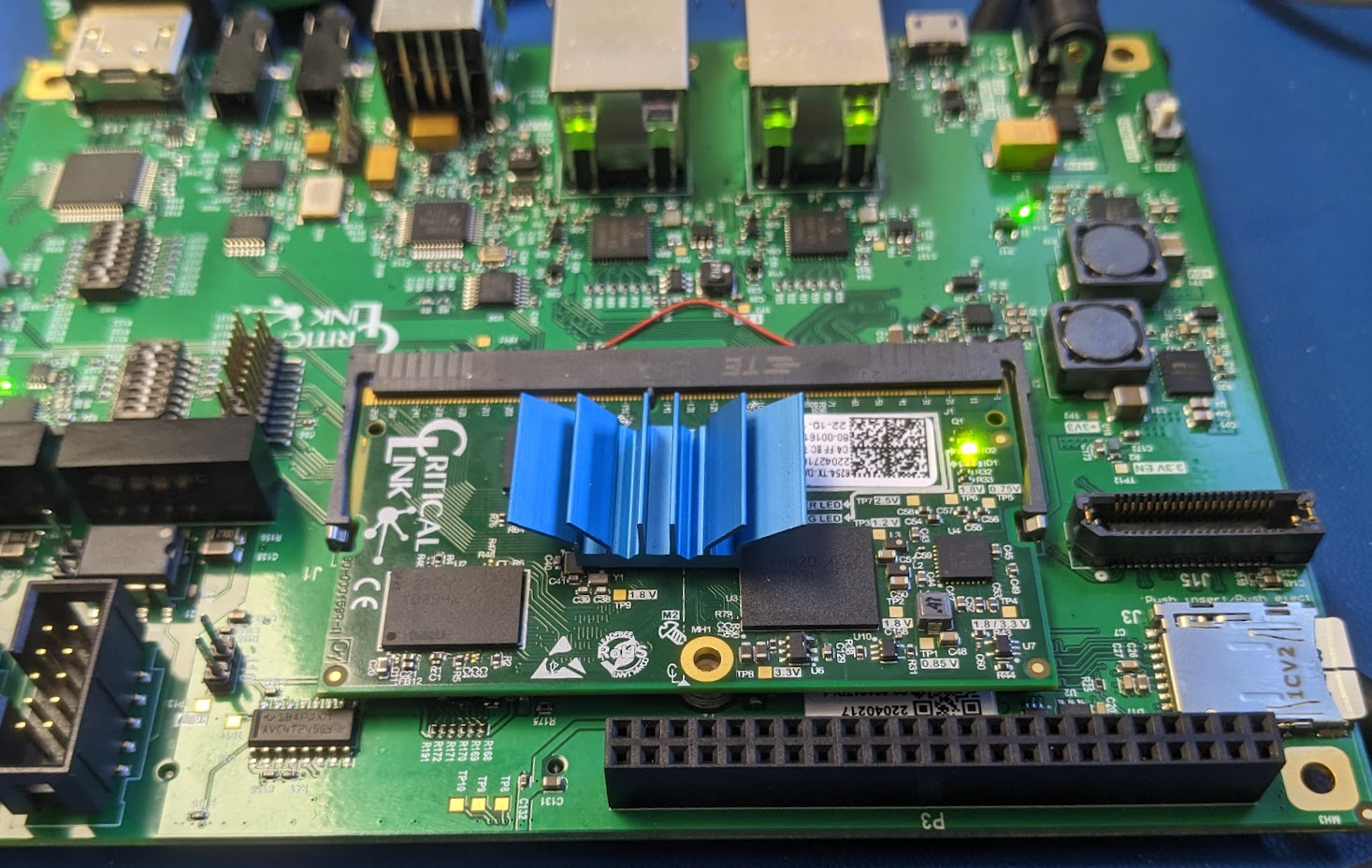
All of the data supplied on this webpage had been collected on the MitySOM-AM62x development kit with a 6254-TX-DAD-RI SOM.
Power consumption
Power consumption reported on this page represents the measured +3.3V voltage and current using the LTC2945HUB-1 (U1) on the Development Kit, which monitors the +3.3V rail fed to the MitySOM-AM62 via the DDR4 SODIMM interface.
It should be noted that some of the power reported includes the 1.8V output supply delivered by the SOM back to the Development Kit baseboard in order to supply IO voltages for the Ethernet PHYs and reference voltages for the TFP410 PHY. The delivered power from the 1.8V rail is not measured / included with these results, though it is expected to be less than 200 mW based on the datasheets for these attached devices. Customers planning to leverage significant current from the 1.8V supply provided by the SOM should consider that the PMIC on the SOM may consume additional power (approximately 10-15% as the supply is typically 85-90% efficient).
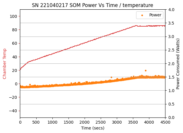
Measurements so far indicate an overall SOM power consumption that ranges between 1W and 3W when powered on (not sleeping, etc.) under various load conditions.
Environmental Testing
Stress Testing
The MitySOM-AM62 SOM (6254-TX-DAD-TI) was placed in the MitySOM-AM62 Development Kit and loaded into the environmental chamber with the following configuration:
- Industrial Temperature micro-SD used for boot media and reference filesystem
- Industrial Temperature USB stick loaded into one of the USB 2.0 HUB positions
- External USB connection made to PC (MitySOM-AM62 USB 2.0 Dual Role port configured as an RNDIS network device)
- Both ethernet ports connected to an internal network at 1 Gbps link rates.
- Micro-USB console port connected to external PC for console monitoring.
- Monitor (1920x1080p) connected to HDMI port.
Stress Test software was enabled on the MitySOM-AM62 to perform the following operations (continuously) during test:
- Running the "memtest" application on 256 MB of DDR4 memory
- Running nandtest continuously on the MitySOM-AM62 OSPI NOR partitions
- Running stress-drive tests on a USB stick partition.
- Running stress-drive tests on a MitySOM-AM62 eMMC device partition.
- Running stress-drive tests on a micro-SD card partition.
- Running the TI provided 3D walking man OpenGL graphics program
- Running a stats collection script which gathers CPU temperature, power / current draw, and CPU utilization
- Running iperf on eth0
- Running iperf on eth1
- Running iperf on usb0, configured as an RNDIS network device
Note: the OLDI interface was not run during this test. Running the OLDI interface will draw additional power in order to drive the LVDS output links.
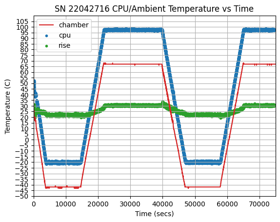
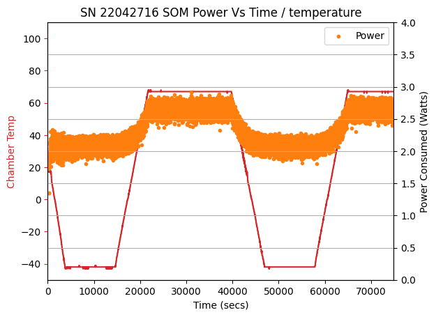
The system was allowed to run while the environmental chamber ranged from -45C to +65C, including soaks at each end of the range.
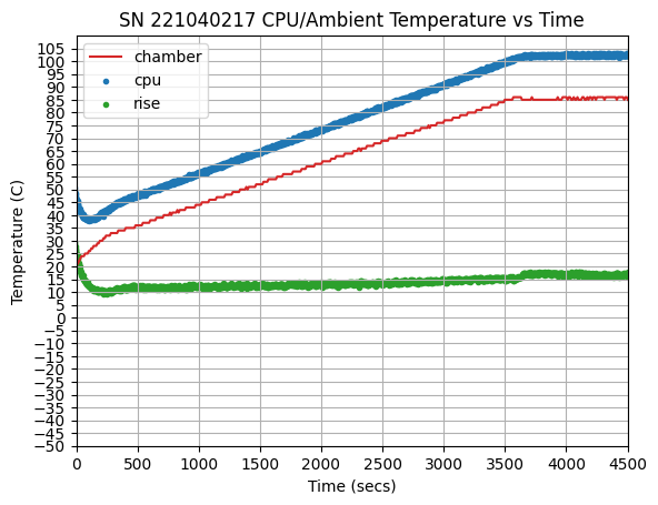
The figures below show the temperature of the AM62x (die temperature as reported by the kernel software), the chamber, the computed temperature rise, and the power consumed by the SOM.
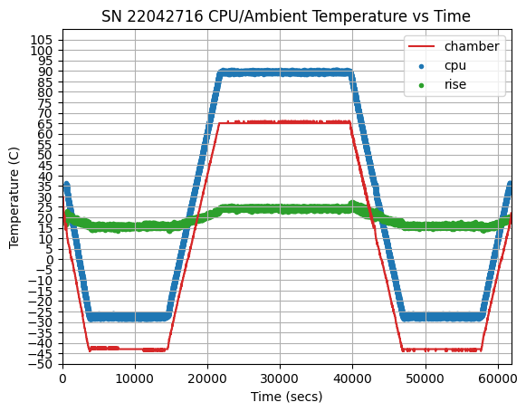
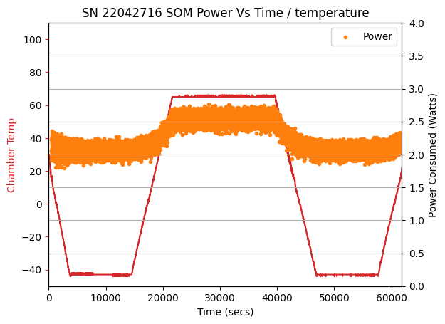
Stress Testing with passive heat sink attachment
As shown in the above results, when operating under relatively heavy load with the development kit, there is an approximate 35C rise in CPU die temperature over ambient temperature above 50C. The rise exceeds the maximum specified junction temperature of the processor (105C for industrial grade parts) when the ambient environment reaches approximately 70C. The testing was repeated with one unit using an off-the-shelf (ATS-52170B-C1-R0) passive heat sink attached to the processor. Results are included in the figures below. The overall CPU rise dropped to between 22-27C, which should allow ambient operation at up to approximately 78-80C. Under heavy loads, additional thermal management (e.g., a fan, or a larger heat sink, etc.) will be required.
Idle Testing with passive heat sink attachment
In this case, the same heat sink was attached as previously mentioned and the system was booted to Linux and no additional software was run (beyond the data logging software) while the chamber was ramped from +20 to +85C. The CPU governor selected was "on-demand", and the typical operating frequency selected was in the range of 200-400 MHz. From the figures, the power consumption of the SOM is much lower, and the unit was able to run at temperatures up to 85C ambient (though, just barely within the CPU 105C limit).
CPU Max Frequency vs. CPU temperature
Measurements where taken while running a stresstest and using cpu fan heatsinks FJ23 23mm BGA 5V Fansink with stick-on-pad.
The following tests were conducted using five 6254-TX-X9D-RI SOMs.
Ambient = 85C| CPU Max Frequency (Hz) | SOM0 CPU temp (C) | SOM1 CPU temp (C) | SOM2 CPU temp (C) | SOM3 CPU temp (C) | SOM4 CPU temp (C) |
| 1400000 | 108.8 | 102.7 | 104.8 | 102.1 | 103.8 |
| 1250000 | 102.1 | 98.4 | 100.3 | 97.5 | 99.8 |
| 1000000 | 101.4 | 98.2 | 99.9 | 97.2 | 99.1 |
| 800000 | 101 | 97 | 99 | 96.1 | 98.4 |
| 600000 | 100 | 96.5 | 98.2 | 95.9 | 97.3 |
| 400000 | 99.4 | 95.7 | 97.5 | 95.8 | 97 |
| 200000 | 97.7 | 94.5 | 97 | 94.5 | 95.7 |
echo <maxFreq> > /sys/devices/system/cpu/cpufreq/policy0/scaling_max_freq
Additional heat sinks
| Type | Model | Size | Idle Cpu Temp @ 65C Amb | Stress Cpu Temp @ 65C Amb |
| None | None | 90C | 99C | |
| Passive | ATS-52170B-C1-R0 | 17mm X 17mm X 7.5mm | 78C | 90C |
| Passive | ATS_52150B-C1-R0 | 15mm X 15mm X 7.5mm | 85C | 93C |
| Passive | Alum Heatsink for Raspberry PI | 15mm X 15mm X 15mm | 83C | 94C |
| Active | FJ23 23mm BGA 5V Fansink with stick-on-pad | 23mm X 23mm X 21mm | 80C | 87C |
SOM consumption while Sleeping and Powered Down
Tests were performed to measure the power consumed on the MitySOM-AM62x development kit and SOM while the SOM was powered down as well as in sleep mode.
Consumption while SOM is powered Down
In this test, the SOM PMIC was commanded to power down all controlled supplies on the SOM via the poweroff command.
Note the SOM power consumption when off should be limited to the PMIC TPS65217 powered-down power usage which is 6uA. Our current measuring setup wasn't precise enough to measure currents that low.
| Description | Voltage | Current | Power Consumed | Notes |
|---|---|---|---|---|
| DevKit board input | 12V | 0.12A | 1.441 W | The local power supplies, ethernet PHYs, etc., remain powered on the DevKit while the SOM is powered down |
| SOM Input Supply | 3.3V | 1.15mA | 3.75 mW | The LEDS were configured to be disabled for this test |
Consumption while SOM is sleeping
In this test, the SOM was commanded to enter memory sleep for 10 seconds with the following command. In the sleep state, the AM62x processor state is held in memory and the local PMIC power supplies are still enabled. However, the AM62x does shut down many voltage and clock domains in order to reduce overall consumption.
Important Notes for DeepSleep For MitySOM-AM62
root@mitysom-am62x:~# rtcwake -s 10 -m mem
| Description | Voltage | Current | Power Consumed | Notes |
|---|---|---|---|---|
| DevKit board input | 12V | 0.09A | 1.081 W | The local power supplies, ethernet PHYs, etc., remain powered on the DevKit while the SOM is sleeping |
| MitySOM-AM62x Input Supply | 3.3V | 14mA | 46 mW | The LEDS were configured to be disabled for this test |
| MitySOM-AM62A Input Supply | 3.3V | 35mA | 115 mW | The LEDS were configured to be disabled for this test |
| MitySOM-AM62P Input Supply | 3.3V | 14mA | 45 mW | The LEDS were configured to be disabled for this test |